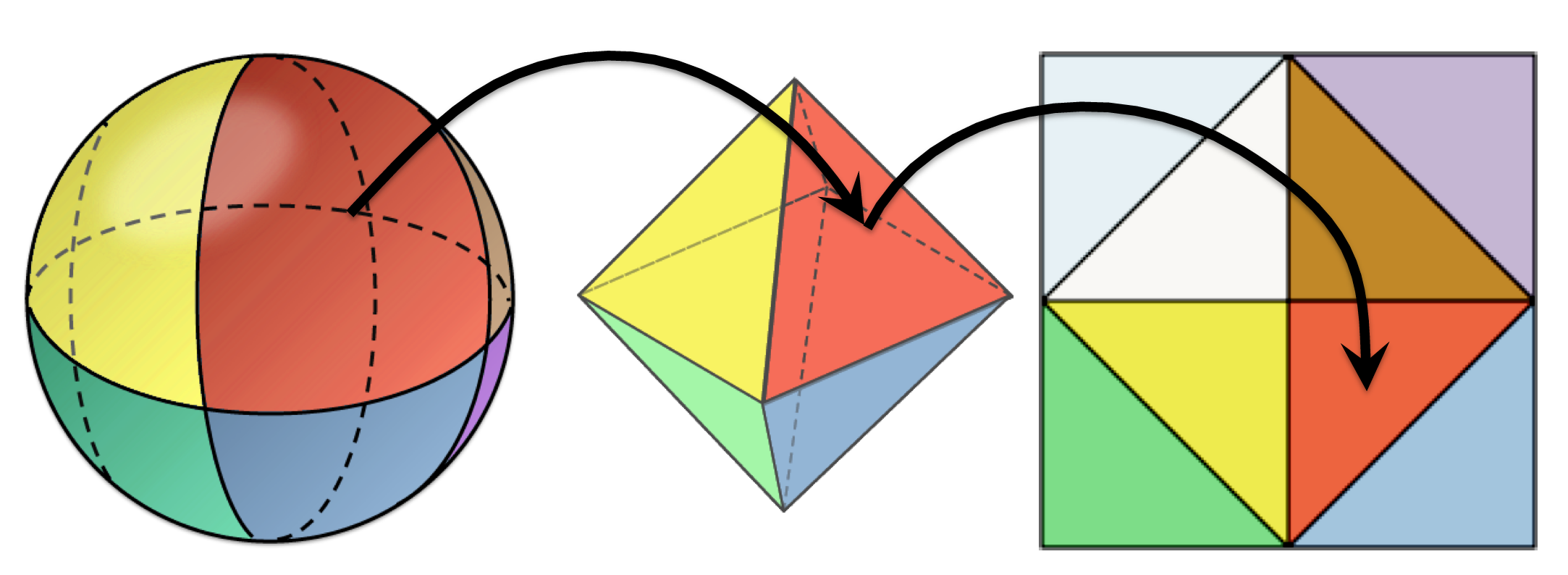
Octahedron encoding (also called octahedral encoding) is a very popular way to encode normals. It’s fast to encode, very fast to decode, has near uniform mapping, and has low error. While writing my last post on meshlet compression, I spent a lot of time looking at that final aspect, the low error. I had three questions I wanted answered: what is the error quantitatively, can that be used to help select the quantization level, and can any further compression be applied? I ended up going down a rabbit hole exploring these questions and thought I would share what I learned along the way. All of the C++ code that was used in the making of this blog post can be found here.
Measuring The Error
The octahedral encoding function takes in a unit length vec3, and returns a vec2 with values from [-1, 1]. Instead of storing two floats, those values are usually then quantized to save space. How many bits should you use when quantizing? Most people just default to 16 bits (8 for each value), but how much error does that give? How does it change as the bit length changes? Well, we can measure that! If we take a unit vector and process it (encode, quantize, and decode), we can then get the angular difference between these two vectors using arc cosine to see how closely they match. If we do that for a million random unit vectors, we can get a good idea of the mean and max angular error for each bit length:
| Bits X | Bits Y | Mean Error | Max Error |
|---|---|---|---|
| 7 | 7 | 0.703610 | 1.905714 |
| 8 | 8 | 0.350526 | 0.946480 |
| 9 | 9 | 0.174814 | 0.473682 |
| 10 | 10 | 0.087357 | 0.235790 |
| 11 | 11 | 0.043663 | 0.117949 |
| 12 | 12 | 0.021842 | 0.058642 |
| 13 | 13 | 0.010909 | 0.029560 |
We can see that increasing the bit length by one in each dimension (therefore quadrupling the total number of possible values), cuts both our mean and max error in half. We’re not required to choose the same number of bits for each dimension though. So what happens if we use a rectangular grid, instead of a square grid?
| Bits X | Bits Y | Mean Error | Max Error |
|---|---|---|---|
| 8 | 8 | 0.350526 | 0.946480 |
| 9 | 8 | 0.273192 | 0.724812 |
| 10 | 8 | 0.246261 | 0.625927 |
| 11 | 8 | 0.237676 | 0.586377 |
| 9 | 9 | 0.174814 | 0.473682 |
We can see that 9 bits in X is only 22% better, instead of the 25% we would like. Increasing it further gives even more diminishing returns, and is also generally pointless: if you have space for 18 total bits, you should just use 9 for X and 9 for Y. If you have the space for an extra single bit, however, it is worth remembering you do get a decent error reduction from it.
So, we found the error and learned that square quantization grids give the best error reduction per bit. Is there any way we can do better, though? Often times compression algorithms have a tradeoff, where the longer you spend compressing, the better the error or compression ratio is. Is there an equivalent here? As it turns out, there is!
Precise encoding
If we think about the encoding process, we map from a sphere to a folded-down octahedron \(\mathbb{R}^3 \rightarrow \mathbb{R}^2\), and then we quantize to integers with our given bit length \(\mathbb{R}^2 \rightarrow \mathbb{Z}^2\). Both of these steps introduce error, though the total error is almost always dominated by the quantization error (\(\mathbb{R}^2 \rightarrow \mathbb{Z}^2\)). The standard way to quantize and dequantize a unorm float x with a bit length of b is as follows:
There are some alternate ways to do it, but they all share the same issue here: they are trying to minimize the error from \(\mathbb{R}^2 \rightarrow \mathbb{Z}^2 \rightarrow \mathbb{R}^2\). What we want to minimize, however, is the angular error after the entire encode and decode process. By quantizing without taking the original vector into account, particularly the step where we blindly round to the nearest integer, we are adding more error. So, instead of blindly rounding, we could choose between the floor and ceil operators based on the round-trip angular error in both dimensions. The code for this is in octahedral_encoding.cpp::OctEncodeUNorm_P here for reference. So what error does this now give us?
| Encoding | Mean Error | Max Error |
|---|---|---|
| 16 | 0.350526 | 0.946480 |
| 16P | 0.327725 | 0.631641 |
| 18 | 0.174814 | 0.473682 |
| 18P | 0.163475 | 0.315057 |
| 20 | 0.087357 | 0.235790 |
| 20P | 0.081684 | 0.158212 |
We can see that the mean error goes down by ~6.5%, and the max error goes down by ~33%, for all bit lengths. That’s pretty substantial! The best part is that decoding this variant is the exact same as before, so the only performance loss is on the encoding side of things, which can often be done offline anyway.
Note: I learned about this precise encoding variant from this 2014 survey paper, so full credit to those authors. It’s a great paper that compares multiple unit vector representations, including octahedral. I’ll discuss the paper’s findings more at the end of this post.
Qualitatively Measuring error
While having exact error numbers is great, they aren’t the most helpful by themselves. We have no frame of reference to know how much error is too much. Unfortunately, the only real way to figure that out is to visualize it and judge it for yourself. I made a shadertoy demo here to do just that. It lets you adjust the bit length with the up and down arrows, and you can hold left mouse button to see precise encoding. Note: it helps to go fullscreen to see the artifacts.
For me, I can easily see the error at 16 bits, have a harder time at 18 bits (but can still see it), and don’t notice it at all starting at 20 bits. The bummer is that precise encoding isn’t ever quite enough to save bits. For example, I can still see the error at 18P, but not with standard 20. In the end, though, the bit length you choose can depend on many different factors and can vary from application to application. Perhaps for your content, 16 or 18 bits is already unnoticeable, especially with precise encoding. I find it helpful to at least have a general starting point though, knowing that I don’t notice artifacts once their average error is below roughly one-tenth of a degree.
Compressing Further
As always with compression, the never-ending question is, “Can we compress it further?” If we look at using octahedral encoding for a single unit vector, then the answer is: “No, not really.” But, what if we had a group of normals that roughly all pointed in the same direction? This is the exact scenario that came up while writing my last post on meshlet compression. If you’re not familiar with them, think of meshlets as tiny submeshes of a larger model. Usually, they’re created so that all of the triangles (usually 32 - 256) within that meshlet are very spatially coherent. The details aren’t important, all you need to know is that very often all of the normals within a meshlet will point in a similar direction.
My first attempt at exploiting this coherency was to find the 2D AABB of the meshlet’s normals in octahedral space. Hopefully that AABB would be small, and then we could use fewer bits for each normal within that meshlet. For example, imagine we would normally use 16 bits for octahedral normals, but we know that every normal within a meshlet encodes to values between [0.375, 0.625]. In that case, we really only need to store values between [0, 0.25] if we also save the meshlet’s offset (0.375). Since we only need to store a quarter of the values, we could lower the bit length from 8 to 6 in each dimension, saving 4 bits per normal, without any loss in precision.
Immediately, however, we run into two issues:
- The traditional octahedral encoding function maps the +Z axis to the center. This also means that the opposite axis, -Z, maps to the four corners. So any group of normals that faces mostly -Z will have a full-sized AABB.
- Even within the +Z hemisphere, it turns out the AABB is almost never small anyway!
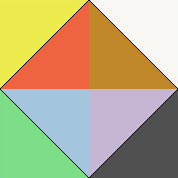
The first issue is easy to get around: you could rotate the normals after decoding, similar to normal mapping except on a per-meshlet tangent space. We normally already store the meshlet’s direction for culling anyway, so there is half of it. If that’s too expensive, another option is to change the encoding to center any of the 6 axes (+X, -X, +Y, -Y, +Z, -Z). You have to change the decoding step too, but it’s the same cost with whatever axis you pick. The code for these variants can be found here. If we visualize each of the 6 encodings, it would look like this:
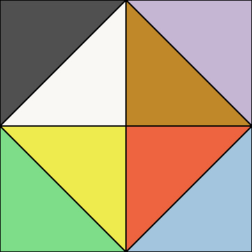
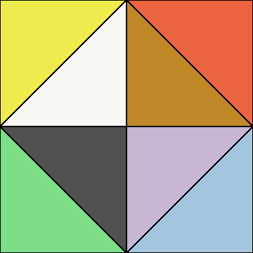
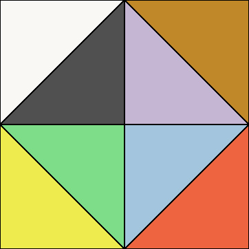
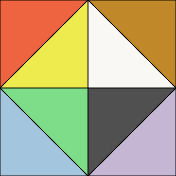
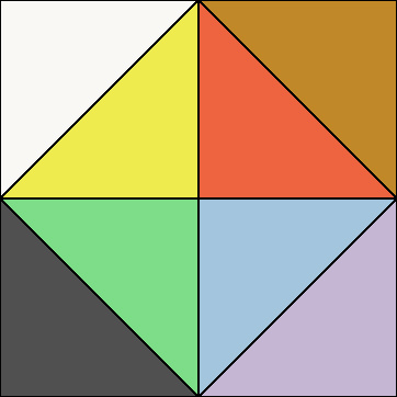
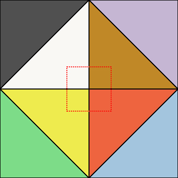
With this, it opens up the option to pick the orientation that gives you the smallest AABB for each meshlet individually. Let’s talk about the second issue, though, where the AABB is rarely small anyway. The reason is a lot easier to see if we label the different triangles in the octa diagram:
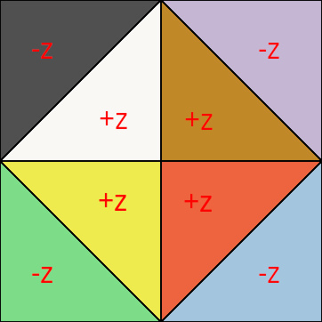
Even though we would like to save at least one bit if we’re restricted to the +Z hemisphere, we can’t: the diamond shape itself means that the AABB for +Z hemisphere alone is already full-sized, [0, 1]. On top of that, you can only save bits with this method if the AABB size is smaller than 0.5, so in practice it just doesn’t happen as often as I’d like. It does still save memory on average, but very little. So, is there anything we can do about this? Well, yes! If a diamond shape is bad, then why not avoid it in the first place?
Rotated Octahedron Encoding
At the end of the day, mapping an octahedron down onto a 2D plane is really just fitting 8 triangles into a rectangle. There is no reason we have to place them to form this diamond shape. So, why not just tweak our encoding such that it rotates the diamond by 45 degrees and becomes a square? This is actually something people already do for octahedral environment maps, since usually only need the top hemisphere of an environment map. So how do we do that? Well, a 2D rotation is:
\[ \begin{aligned} x' &= x*cos( \theta ) - y*sin( \theta )\\ y' &= x*sin( \theta ) + y*cos( \theta ) \end{aligned} \]When we encode, we want to rotate by -45 degrees (or +45, it doesn’t matter), and then when we decode, we will do the opposite:
\[ \begin{aligned} x' &= \frac{\sqrt{2}}{2} * (x + y)\\ y' &= \frac{\sqrt{2}}{2} * (-x + y) \end{aligned} \]We can actually ignore the \(\sqrt{2}/2\) during the encoding step because it’s just a scalar, and we have to rescale the entire thing to be [0, 1] anyways. When we decode though, we will have to compensate by multiplying by \(\sqrt{2}/2\) twice, which is just 0.5. So this will make the inner diamond a square, but what about the -Z hemisphere? Well, this will also make it a square, and we just need to offset it so that we store it next to the +Z hemisphere.
So the final encode and decode functions would look something like this:
vec2 Encode( vec3 v )
{
    v = v / ( Abs( v.x ) + Abs( v.y ) + Abs( v.z ) );
    vec2 oct;
    oct.x = v.x + v.y;
    oct.y = -v.x + v.y;

    if ( v.z > 0 )
        oct.x += 2;
    oct.x = 0.5f * oct.x - 0.5f; // from [-1,3] to [-1, 1]

    return 0.5f * oct + + 0.5f; // from [-1, 1] to [0, 1]
}

vec3 Decode( vec2 oct )
{
    float hemisphere = 1;
    oct.x *= 2; // [0, 2]
    if ( oct.x > 1 )
    {
        hemisphere = -1;
        oct.x -= 1; // [1, 2] -> [0, 1]
    }
    vec2 octaPos = 2.0f * oct - 1.0f; // [0, 1] -> [-1, 1]

    vec3 v;
    v.x = 0.5f * ( octaPos.x - octaPos.y );
    v.y = 0.5f * ( octaPos.x + octaPos.y );
    v.z = hemisphere * ( 1.0f - Abs( v.x ) - Abs( v.y ) );
    return Normalize( v );
}
If you know you only need the +Z hemisphere, then it gets simpler:
vec2 Encode_Hemisphere( vec3 v )
{
    v = v / ( Abs( v.x ) + Abs( v.y ) + Abs( v.z ) );
    vec2 oct;
    oct.x = v.x + v.y;
    oct.y = -v.x + v.y;
    return 0.5f * oct + + 0.5f; // from [-1, 1] to [0, 1]
}

vec3 Decode_Hemisphere( vec2 oct )
{
    vec2 octaPos = 2.0f * oct - 1.0f; // [0, 1] -> [-1, 1]
    vec3 v;
    v.x = 0.5f * ( octaPos.x - octaPos.y );
    v.y = 0.5f * ( octaPos.x + octaPos.y );
    v.z = 1.0f - Abs( v.x ) - Abs( v.y );
    return Normalize( v );
}
The full encode function would give you a diagram like this, with the +Z hemisphere on the left, and the -Z on the right:
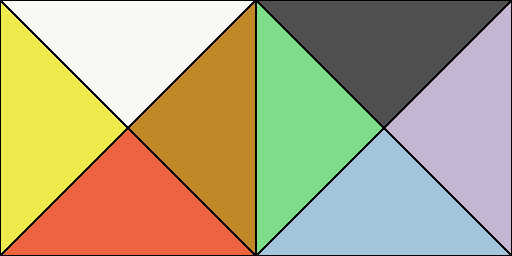
This is good! We slightly increased the decoding cost, but now our AABBs can be smaller as well. Since we’ve changed the encoding and decoding math a bit, let’s double-check what the error is now, though.
Measuring Rotational Error
Running our rotated variant through the same random vectors as before, we get:
| Encoding | Mean Error | Max Error |
|---|---|---|
| 14R | 0.773113 | 1.984227 |
| 16R | 0.385242 | 0.986854 |
| 18R | 0.192359 | 0.492528 |
| 20R | 0.096009 | 0.246419 |
| 22R | 0.047993 | 0.123342 |
We see that the mean error has increased by 10%, and the max error by 4.5% compared to the non-rotated encoding. This makes some amount of sense– we saw earlier that if the grid wasn’t a perfect square, the error increased. While we are evenly dividing the bits here, the diagram itself is now a rectangle, so it’s not too surprising the error increased a little. What if we only use the upper hemisphere though?
| Encoding | Mean Error | Max Error |
|---|---|---|
| 14RH | 0.501312 | 1.099875 |
| 16RH | 0.249797 | 0.546843 |
| 18RH | 0.124669 | 0.273832 |
| 20RH | 0.062234 | 0.136537 |
| 22RH | 0.031113 | 0.068080 |
Now the mean error has dropped by 29% and the max error by 42%! That’s enough to potentially lower the bit count: regular encoding with 18 bits was already hard to notice, so using 18RH could potentially be good enough to not notice at all. Let’s see how much using precise encoding improves things too:
| Encoding | Mean Error | Max Error |
|---|---|---|
| 14RH | 0.501312 | 1.099875 |
| 14RHP | 0.499686 | 1.099736 |
| 16RH | 0.249797 | 0.546843 |
| 16RHP | 0.249003 | 0.546843 |
| 18RH | 0.124669 | 0.273832 |
| 18RHP | 0.124272 | 0.273814 |
Wait… what? It basically doesn’t help at all, outside a handful of normals? “Surely I just have a bug somewhere,” I told myself and spent a long time looking for a bug. Nothing was popping out at me though, and any checks I did seemed correct. Finally, I did an exhaustive search: change the encoder to loop over every single possible encoding (2^16) and pick the best one. The result? The same thing. There is no bug, it just doesn’t improve things much for rotated octahedral. To understand why this is the case, we need to dig deeper into the error distribution.
A Hard Look At Precise Encodings
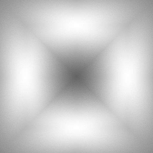
Let’s visualize the error for the regular encoding. We’ll generate millions of unit vectors, find their max error after encoding decoding, and then splat them onto an image using their encoded position as the UV coordinate (pre-quantization):
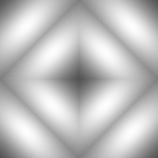
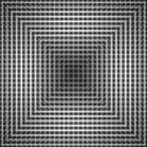
This image is 512 x 512, using 18-bit encoding, which means that one texel covers one quantized value or “cell”. What if we wanted to visualize the error within a single quantized cell though? Many vectors will be quantized to the same cell, with varying errors. To see that, let’s drop the encoding to 10-bit so that each quantized cell will map to a 16 x 16 square of texels:

We can see that the error is lowest along the diagonals of each cell, forming a sort of diagonal oval shape. This makes some sense– it’s following the same diamond shape as the rest of the encoding. The further you move from that, the higher the error is. Now, let’s visualize what happens if we turn on precise encoding, still with 10-bits:
Click on the image, and use the left and right arrow keys to flip between the two images. You’ll notice that within a cell, the corners that were previously very bright are now much dimmer, while the already dark centers of each cell stay the same. Why is that? Well, if a vector encodes into the dark oval of a cell, then it already has low error. Moving to a neighboring cell would only increase the error, and since it’s already as low as it can be, it makes sense it doesn’t change color. But if a vector has high encoding error? Then it can be better to use a neighboring quantized value (move to an adjacent cell) instead, if its dark (low error) oval is close to that vector’s original texel. That’s the key piece– it will only benefit moving to a neighboring cell if it’s aligned with that cell’s low-error region (dark oval).
Confusing? Let’s visualize this. We define the movement as the difference between the precise and regular texel coordinates. We can assign each of these movements a different color, and we get the following:
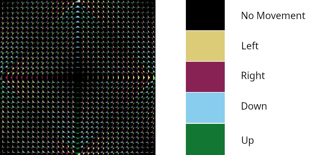
It’s exactly what we would expect: texels that are already in the dark oval region never move, but texels that are bright will move to the closest dark oval they’re neighboring! We also see that we never get diagonal movement, because the texels diagonally are always bright too. Now, the whole point of this was to figure out why rotational precise encoding doesn’t work, so let’s try visualizing rotational error:
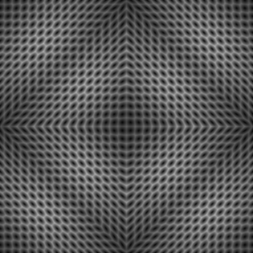
Seems totally fine, what about when we try to visualize the error within each cell again?
And here lies the problem! See the orientation of the dark ovals within each cell? They are no longer diagonal. This means that when precise encoding is looking for neighbors with lower error, it won’t find any. Previously, the fact that the ovals were diagonal meant that bright pixels in the corners of each quantization cell always had some neighboring dark oval that was touching them. With rotational encoding though, the ovals don’t reach the corners at all. So the bright pixels at the edges of quantized cells only border other bright pixels, meaning they will rarely move to a different neighbor because they’re bad too. What I initially thought was a bug in my programming turned out to just be something inherent in the rotation itself: rotating the encoding also rotates the error distribution away from the corners, which was the only reason it worked so well with non-rotational encoding.
The Slight Sticking Point
With all of this, there is one thing that irks me something fierce. That 2014 survey paper I mentioned earlier? It actually measures the error of octahedral encoding, among others. The issue? I cannot replicate their numbers for octahedral encoding for the life of me. It’s close: the average mean error I get is 4-4.5% higher than what the paper reports. This is true regardless of whether using precise encoding or not. I’ve followed the paper’s steps the best I can, and I’ve tried so many different things: different random number generators, float64 vs float32, different quantization methods, unorm vs snorm, different compiler flags, the supplemental code provided by the authors themselves, and more. All of it to no avail.
Side note: the code they provide for the non-precise encode function is fine. The code they provide for precise encoding though, has 2 bugs in it, so the numbers make no sense until you fix those. Upon fixing them though, it still matches my own code at 4.5% higher
It gets weirder too: it’s only the octahedral mean error numbers I cannot recreate. With the same framework, the octahedral max error I get is within \(\pm\) 0.6%, and other methods like spherical encoding match perfectly. So, I don’t know what to make of that. I think my error analysis still stands on its own, and the encodings are very much usable. I just wish it matched what the paper reported too.
Conclusion
So we’ve found the error quantitatively and qualitatively for octahedral encoding. We learned there is a precise encoding variant that helps reduce the max error moderately and reduces the mean error modestly. We figured out how to rotate the encoding to help save space when we only care about one hemisphere, and showed why precise encoding doesn’t work for rotated encodings. We also learned that while people default to encoding the +Z axis in the center, we can choose any of the 6 axes.
That ended up being a lot longer than I thought! Hopefully you learned a few things in there, though. Leave a comment if you have any questions or want to chat about this!