Render Graphs, or “Task Graphs,” rapidly became the standard in the industry ever since Yuriy O’Donnell’s 2017 GDC presentation on Frostbite’s FrameGraph. They provide many benefits, like handling all of the synchronization barriers and resource transitions, reordering tasks for increased performance, reducing memory usage via resource aliasing, and the list goes on for miles. They’re nearly mandatory for large projects these days, given how verbose and error-prone these things would be if done manually with modern APIs like Vulkan and DX12.
This article isn’t to explain their benefits, or how they work, or to discuss their designs from a high level; there are plenty of great resources out there already that do that. Rather, this article is to help fill a smaller niche that I don’t see as many people talk about: what are some concrete examples of task graphs for smaller projects, like hobby game engines? It feels like all too often articles about task graphs immediately dive into topics like acyclic graphs, pruning unreferenced render passes, and parallel command recording on multiple queues. I’d argue, however, that if you’re writing your first task graph system, you absolutely shouldn’t start with any of those things. At least for your personal projects, you were probably never bothered by suboptimal task ordering, had no unreferenced render passes, and had a lot of it single-threaded already. Even professionally, I still don’t think it makes sense to immediately write those features unless you have a huge project that has been optimized a lot.
In this article, I’ll describe the task graph I made for my hobby engine Progression. It keeps things simpler by not adding a lot of commonly talked about features: it doesn’t reorder tasks at all, doesn’t do any task pruning, doesn’t rebuild every frame, and only uses one queue. Instead, it just focuses on the core pain points introduced by modern APIs like Vulkan: synchronization, resource transitions, and resource allocation. Out of all the fancier features, I only chose one to start with: resource memory aliasing. I might build on this in the future, of course, but I think it’s already tremendously helpful as-is, and worth sharing. All of the code for this can be found here.
Building
The task graph in Progression has two steps: building and compiling. The build step is where all of the passes are defined, all of their inputs and outputs, the resource formats, sizes, etc. I think it’s simplest to just show a real example of how it’s used and walk through it from there:
TaskGraphBuilder builder;

ComputeTaskBuilder* cTask      = builder.AddComputeTask( "FrustumCullMeshes" );
TGBBufferRef indirectCountBuff =
    cTask->AddBufferOutput( "indirectCountBuff", VMA_MEMORY_USAGE_AUTO_PREFER_DEVICE, sizeof( u32 ), 0 );
TGBBufferRef indirectDrawBuff =
    cTask->AddBufferOutput( "indirectDrawBuff", VMA_MEMORY_USAGE_AUTO_PREFER_DEVICE,
                            sizeof( GpuData::MeshletDrawCommand ) * MAX_MESHES_PER_FRAME );
cTask->SetFunction( ComputeFrustumCullMeshes );

GraphicsTaskBuilder* gTask = builder.AddGraphicsTask( "DrawMeshes" );
gTask->AddBufferInput( indirectCountBuff, BufferUsage::INDIRECT );
gTask->AddBufferInput( indirectDrawBuff, BufferUsage::INDIRECT );
TGBTextureRef litOutput  =
    gTask->AddColorAttachment( "litOutput", PixelFormat::R16_G16_B16_A16_FLOAT, SIZE_SCENE(), SIZE_SCENE() );
TGBTextureRef sceneDepth =
    gTask->AddDepthAttachment( "sceneDepth", PixelFormat::DEPTH_32_FLOAT, SIZE_SCENE(), SIZE_SCENE(), 1.0f );
gTask->SetFunction( MeshDrawFunc );

...
First, there is the TaskGraphBuilder object. It’s responsible for creating the list of all the tasks and resources defined. You’ll notice most of the builder-specific objects either have the postfix Builder or the prefix TGB (for task graph builder). Four possible task types that can be created: compute, graphics, transfer, and present. Each task inherits from a base TaskBuilder. This is mainly so that the TaskGraphBuilder can hold a single list of pointers to all the tasks, and it also holds some basic info about each task, like the name, type, and index into the builder’s list. In the above example, a compute task is first defined, which we can dive into next.
Compute Tasks
Compute tasks need support for both buffers and textures for either input or output being added. Graphics tasks also need this functionality, so there is an intermediate builder class that they both inherit from:
class PipelineTaskBuilder : public TaskBuilder
{
public:
    PipelineTaskBuilder( TaskGraphBuilder* inBuilder, u16 taskIndex, TaskType taskType, string_view inName );

    TGBTextureRef AddTextureOutput( string_view name, PixelFormat format, const vec4& clearColor,
        u32 width, u32 height, u32 depth = 1, u32 arrayLayers = 1, u32 mipLevels = 1 );
    TGBTextureRef AddTextureOutput( string_view name, PixelFormat format,
        u32 width, u32 height, u32 depth = 1, u32 arrayLayers = 1, u32 mipLevels = 1 );
    void AddTextureOutput( TGBTextureRef& texture );
    void AddTextureInput( TGBTextureRef& texture );

    TGBBufferRef AddBufferOutput( string_view name, VmaMemoryUsage memoryUsage, size_t size, u32 clearVal );
    TGBBufferRef AddBufferOutput( string_view name, VmaMemoryUsage memoryUsage, size_t size );
    void AddBufferOutput( TGBBufferRef& buffer );
    void AddBufferInput( TGBBufferRef& buffer, BufferUsage usageForThisTask = BufferUsage::STORAGE );

    vector<TGBBufferTaskInfo> buffers;
    vector<TGBTextureTaskInfo> textures;
};
Notice how for both AddBufferOutput and AddTextureOutput there are three variants: one that defines all the creation parameters (first use of resource), one that defines all of the creation parameters but also adds a clear value/color (again, first use of resource), and one that just takes in a reference to an already created resource. If we look at one of the AddBufferOutput functions, they have three jobs:
- Create a new
TGBBufferobject, which stores all of the info needed to create the resource later. This is stored inTaskGraphBuilderand is shared across all tasks. - Create a new
TGBBufferTaskInfoobject, which is stored directly in thePipelineTaskBuilder. This holds a reference to the actualTGBBufferresource but also stores extra information relevant to this specific task: does it need to be cleared, whether the resource is being read from or written to, and how it’s used in this task (only used for giving better pipeline stage barriers). - Update the buffer’s lifetime. This is because I am doing memory aliasing, so I need to know what the first and last task each resource is used in.
As you can see below, PipelineTaskBuilder covers basically all of the functionality that the compute task builder needs. The only missing piece is that the user also needs to supply the function to be called when the task is being executed every frame. I’ll explain this more later, but it’s basically just the function that fills out the command buffer and calls the final dispatch call.
class ComputeTaskBuilder : public PipelineTaskBuilder
{
    ComputeFunction function;
public:
    ComputeTaskBuilder( TaskGraphBuilder* inBuilder, u16 taskIndex, string_view inName );
    void SetFunction( ComputeFunction func ) { function = func; }
};
Graphics Tasks
The GraphicsTaskBuilder is extremely similar to the ComputeTaskBuilder, so I won’t show the code here. It simply adds the ability to add attachments with AddColorAttachment and AddDepthAttachment functions. They follow the exact same pattern as before with three variants: one for creating a new attachment, one for creating and clearing a new attachment, and one for reusing an attachment. It also takes in a function to be called every frame while the task is being executed that will fill out the command buffer and make all the drawIndexed/whatever calls.
Transfer Tasks
Transfer tasks are simply copies and blits on the GPU. So the builder task simply keeps a list of the copies and blits specified. This task does not take in any user function like the compute and graphics tasks, because we can already write the code ahead of time to perform these copies.
class TransferTaskBuilder : public TaskBuilder
{
public:
    TransferTaskBuilder( TaskGraphBuilder* inBuilder, u16 taskIndex, string_view inName );

    void BlitTexture( TGBTextureRef dst, TGBTextureRef src, TextureFilter filter = TextureFilter::LINEAR );
    void CopyBuffer( TGBBufferRef dstBuff, u64 dstOffset, TGBBufferRef srcBuff, u64 srcOffset, u64 size );

    vector<TGBTextureTransfer> textureBlits;
    vector<TGBBufferTransfer> bufferCopies;
};
The transfer task is something I’m sure I’ll have to expand later, for things like specifying texture subregions, mips, etc. It also would be really nice to have some easy way to do GPU to CPU transfers for debugging, which could maybe be done nicely with these transfer tasks.
Present Tasks
These are very simple. The only member function they have is SetPresentationImage, which just takes in a TGBTextureRef to the texture you want to present to the screen. There is no function to run each frame; the only thing this task does is transition the image’s layout to VK_IMAGE_LAYOUT_PRESENT_SRC_KHR.
External (Non-Transient) Resources
One important point here is that any resource declared using the methods above is transient. This means they are expected to only have lifetimes less than or equal to one full frame. This also means that any resources that need to be persistent, like TAA history buffers, need to be created externally. You also sometimes have resources that are created before the task graph is created, like the swapchain. While these allocations might be handled externally, we still want those resources to be valid inputs, outputs, and attachments for any task in the graph. The way I handle this is by letting the user register external resources. One example would be:
TGBTextureRef swapImg = builder.RegisterExternalTexture( "swapchainImg",
    swapchain.GetFormat(), swapchain.GetWidth(), swapchain.GetHeight(), 1, 1, 1,
    []() { return rg.swapchain.GetTexture(); } );

...

ComputeTaskBuilder* cTask = builder.AddComputeTask( "post_process" );
cTask->AddTextureInput( litOutput );
cTask->AddTextureOutput( swapImg );
cTask->SetFunction( PostProcessFunc );
So, it looks the same as specifying a regular texture inside of a task, except we now also supply a function pointer that returns the desired resource when called. Why a function, and not just supply the resource handle immediately? Because sometimes, like with swapchain images, the resource changes every frame. So, every time the task graph is executed, the first thing it does is call all resource external functions to update the task graph’s internal copy of those resources.
Compilation
Now that we have the tasks and resources defined in the TaskGraphBuilder, it’s time to create the final TaskGraph object by compiling the task graph builder. By that, I mean create all of the GPU resource handles, do the memory aliasing, create the synchronization barriers, and create the final, non-builder, task objects that will be used in every frame. All of the code for this is in r_taskGraph.cpp, look for TaskGraph::Compile.
Resource Creation
The first step is to create all of the textures and buffers used by the task graph, which is done in TaskGraph::Compile_BuildResources. This simply loops over all the TGBTexture and TGBBuffer resources in the builder and creates the corresponding renderer objects Gfx::Texture and Gfx::Buffer that have the actual GPU handles. The resource handles are created with vkCreate[Image/Buffer], but the resources aren’t bound to any device memory just yet; that is done later during memory aliasing.
The memory aliasing does make this a little more complicated than it normally would be. The code here fills out all of the Texture and Buffer parameters directly instead of using the standard Device::New[Texture/Buffer] functions because those allocate and bind the device memory immediately. We also need to create a ResourceData for each aliasable resource, which is a reference to the resource and its lifetime.
For external resources, it’s slightly different. Their allocation happens externally, so they skip calling vkCreate[Image/Buffer] and skip creating a ResourceData. They do, however, still fill out all the info they can in the Gfx::Texture and Gfx::Buffer objects, and are stored in the same list as the transient resources. This is so that there is a unified API later during task graph execution:
Buffer& GetBuffer( TGResourceHandle handle );
Texture& GetTexture( TGResourceHandle handle );
During task execution each frame, they can use these functions to get the handles to their input and output resources, regardless of whether the resource is external or internal. As mentioned a few sections earlier, these slots that hold external resources get updated each frame, which also allows us to have this unified API.
Memory Aliasing
I’ll go through how I do aliasing but forewarning that it’s a bit messy. I wanted to give it a shot without looking anything up, so it’s not the best. It does work, however, and the code can be found r_tg_resource_packing.hpp and r_tg_resource_packing.cpp. You can skip this section if you’re not interested in aliasing.
General Idea
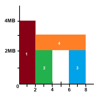
You can view memory aliasing as a 2D rectangle packing problem. The X axis is the task index, and it goes from 0 to the final task’s index. The Y axis is the amount of memory. So, each ResourceData we created earlier actually defines a rectangle in this coordinate space. For example, if we had a 4MB texture that was used in tasks [0, 1] inclusively, then that defines a rectangle of height 4MB and width 2, starting from task 0. That means we need to allocate at least 4MB of memory, which we will call a MemoryBucket. We then place our 4MB texture rectangle inside of this bucket. If we stop here, that would mean regular, non-aliased resources. We can, however, pack more rectangles inside of the bucket, so long as they do not overlap each other at all. For example, if we had two buffers of size 2MB that were used in tasks [2, 3] and [6, 7] respectively, we can pack them vertically in our bucket from Y=[0, 2MB] and Y=[2, 4MB]. This is depicted below (excuse my MS Paint graphics):
Structure
This is where it gets a little messy. At the highest level, we pack resources into MemoryBuckets. These buckets keep track of occupied regions on the X axis, which I call TimeSlices. Each TimeSlice then keeps track of the used regions along the Y axis as a list of Blocks, which are just offset and size pairs. If it’s confusing, the TLDR is that we just need some system to keep track of where the free rectangles are in our bucket.
Algorithm
I’m sure there are better methods, but the way I did it is the greedy O(N^2) approach:
- Sort the
ResourceDataobjects from largest to smallest. - Loop through all of the
ResourceData:- Has this resource been placed into a bucket yet? If yes, then skip until we get an unplaced resource.
- Create a bucket with the same size as the current resource and place the resource inside of it. This means our bucket has one
TimeSliceso far, and that slice has no free blocks in it (because it’s the same size as the bucket). - Now loop over all remaining resources and try to fit them into the current bucket (see
MemoryBucket::AddResource). This is the hardest part, bookkeeping-wise. It works by:- Keep track of which blocks on the Y axis are free so far in a list. At the beginning, we assume the entire region from [0, bucketSize] is free, so there is only one element in the list.
- Loop over all of the time slices in the bucket and find which ones overlap with our current resource (on the X axis). A single resource could overlap many time slices.
- For each overlapping time slice, update our list of free blocks to remove any regions that would overlap with the Blocks in these time slices.
- If there are any free regions left that are at least the size of our resource, we can fit the resource in our bucket. There can be multiple offsets (Blocks) that would fit the resource. In that case, I always choose the one with the lowest offset.
- Go back through the overlapping time slices and update their free regions to account for adding the current resource.
- Add new time slices for regions that previously had no resources in them.
The last couple steps can be slightly confusing, so think of the image example above. After the first three resource are packed, we need to add the fourth (orange) resource. There will be three time slices at this point. The first one doesn’t get touched, but the second and third ones need to be updated to show that the block from [2, 3MB] is no longer free. We also need to add a new time slice from [4,5], with openings from [0, 2MB] and [3, 4MB], since no time slice existed there before.
I liked doing it this way because while the bookkeeping was complicated to track all of the free regions, the idea is pretty straightforward. It also means we’re allocating memory for as few large resources as we can, hopefully saving a lot of space.
Final Steps
The final step is to actually allocate GPU memory and bind resources to it. I use VMA for memory management, which makes this part a lot easier. I highly recommend it. What we do here is loop over each MemoryBucket and allocate one chunk of memory to it using vmaAllocateMemory. Then, we loop over each resource in that bucket and either call vmaBindImageMemory2 or vmaBindBufferMemory2 depending on the resource type, to actually bind the resource to that chunk of memory. These functions conveniently take in the resource Y offsets that we calculated during packing to keep everything non-overlapping. The final thing we do is allocate all of the VkImageView’s, since Vulkan doesn’t let you do that for a VkImage until it has some memory backing it.
One small detail I didn’t mention earlier is that some resources have alignment and memory type requirements. So during the packing process, when you’re calculating if 2 blocks overlap, you have to take their aligned offsets and sizes into account. You also have to check if the bitwise AND between their VkMemoryRequirements::memoryTypeBits and if they result in 0, you cannot pack them together at all.
Synchronization and Tasks
Now that all of the resources are created and allocated, the final thing to do is to create the tasks and any barriers necessary. In my opinion, this is where task graphs really shine. Since all of the resources and their usages are defined up front, we can deduce the necessary barriers automatically by tracking how each resource is used, from task to task. This tracking is done by creating a list of objects to store a resource’s
struct ResourceTrackingInfo
{
    ImageLayout currLayout   = ImageLayout::UNDEFINED;
    u16 prevTask             = NO_TASK;
    TaskType prevTaskType    = TaskType::NONE;
    ResourceState prevState; // read, read_write, write
    ResourceType prevResType = ResourceType::NONE; // buffer, texture, color attach, etc
};
I don’t do anything fancy here, and really just walk through each case for each task. The code is pretty verbose (see r_taskGraph.cpp::Compile_SynchronizationAndTasks), but I’ll show a couple small examples from the Compile_ComputeTask code path for clarity:
for ( const TGBTextureTaskInfo& texInfo : bpTask->textures )
{
    TGResourceHandle index          = texInfo.ref.index;
    const TGBTexture& buildTexture  = builder.textures[index];
    ResourceTrackingInfo& trackInfo = builder.texTracking[index];
    ResourceType resType            = ResourceType::TEXTURE;
    ImageLayout desiredLayout       = InferImageLayout( taskType, texInfo.state, buildTexture.format );

    ...

    if ( trackInfo.prevTask != NO_TASK && trackInfo.prevState != ResourceState::READ )
    {
        // barrier to wait for any previous writes to be complete
        VkImageMemoryBarrier2 barrier = GetImageBarrier( index, trackInfo.prevTaskType, trackInfo.prevState,
            trackInfo.prevResType, taskType, texInfo.state, resType, trackInfo.currLayout, desiredLayout );
        pTask->imageBarriers.push_back( barrier );
    }
    else if ( trackInfo.prevTask == NO_TASK )
    {
        // no writes to wait for, but a barrier is still needed to transition the image to the correct layout
        TG_ASSERT( trackInfo.currLayout == ImageLayout::UNDEFINED, "Should be the first use of this texture" );
        VkImageMemoryBarrier2 barrier = GetImageBarrier( index, TaskType::NONE, ResourceState::UNUSED,
            trackInfo.prevResType, taskType, texInfo.state, resType, trackInfo.currLayout, desiredLayout );
        pTask->imageBarriers.push_back( barrier );
    }
    ...
For full details, please see the code. The main thing here in all of these functions is checking to see if the resource is switching to reads or writes, then writing code (if needed) for all of the cases: R->R, R->W, W->W, W->R. I make the assumption that back to back writes need to have a barrier inbetween them, though this would be suboptimal if the shaders actually wrote to different regions of the resource. If the resource is a render target attachment however,
Handling Clears
Each task holds a list of buffer and image barriers to execute before running the actual core function of the task. The compute and graphics tasks also hold lists of any resource clears that need to be performed before the core function is run. Clears can only happen on the first use of the resource, so we don’t need barriers before the clear happens. Well, that is true for buffers, but sadly not for images. To do a generic vkCmdClearColorImage on an image, we need make sure it has ImageLayout::TRANSFER_DST. So have one extra list of barriers for images, that can run before clear operations. This only applies to non-attachment images for the record. Attachments that want to be cleared use VK_ATTACHMENT_LOAD_OP_CLEAR instead of vkCmdClearColorImage. We also still need barriers after the clear happens, to wait for it to be done before reading or writing to those resources.
Render Passes
For graphics tasks, this is also the step that needs to create the render pass, or gather the information needed for the VkRenderingAttachmentInfo if you are using dynamic rendering. This is very straight forward, since we have a list of all the attachments already, and the storeOp and loadOp can easily be deduced. I actually wrote the first iteration of this task graph using render pass objects, and later switched to dynamic rendering. I found that it was basically the same amount of bookkeeping, so there is little impact either way you choose.
Final Notes
There are a couple final things to note here. Ideally we would think about batching barriers together and reordering tasks to minimize the number of barriers and batches. That would give better performance, but again is one of the things I intentionally ignored for this engine. To be honest, it’s also unclear to me how to reorder tasks to minimize both barriers and maximize memory aliasing at the same time. The second thing to note here, is that the barriers need the VkImage/VkBuffer handles. Since we have external resources that don’t supply that handle until execution time, the resource index is instead stored in the barrier handle:
VkImageMemoryBarrier2 barrier{ VK_STRUCTURE_TYPE_IMAGE_MEMORY_BARRIER_2 };
barrier.image         = reinterpret_cast<VkImage>( imageIndex );
Then during execution time, we use that index to lookup the now-valid resource handle and set it appropriately.
Execution
At this point, the task graph is ready to be used during each frame’s rendering. The steps are pretty straight forward:
- Call every external resource’s function to update the task graph’s copy of those resource handles
- Loop over each task in order and do the following:
- Submit any pre-clear image barriers, if the task has any
- Perform any buffer/image clears, if the task has any
- Submit the regular (not pre-clear) buffer and image barriers
- Call the user function in the case of compute and graphics tasks, or perform the transfers for transfer tasks
The last piece to talk about, is how user task functions look. Here is an example from that frustum culling task shown at the beginning of the article:
void ComputeFrustumCullMeshes( ComputeTask* task, TGExecuteData* data )
{

    ...

    CommandBuffer& cmdBuf = *data->cmdBuf;
    cmdBuf.BindPipeline( PipelineManager::GetPipeline( "frustum_cull_meshes" ) );
    cmdBuf.BindGlobalDescriptors();

    struct ComputePushConstants
    {
        VkDeviceAddress cullDataBuffer;
        VkDeviceAddress outputCountBuffer;
        VkDeviceAddress indirectCmdOutputBuffer;
        u32 numMeshes;
        u32 _pad;
    };
    ComputePushConstants push;
    push.cullDataBuffer          = data->frameData->meshCullData.GetDeviceAddress();
    push.outputCountBuffer       = task->GetOutputBuffer( 0 ).GetDeviceAddress();
    push.indirectCmdOutputBuffer = task->GetOutputBuffer( 1 ).GetDeviceAddress();
    push.numMeshes               = meshNum;
    cmdBuf.PushConstants( push );
    cmdBuf.Dispatch_AutoSized( meshNum, 1, 1 );
}
You can see that the function is able to get the task-specific resources directly, like task->GetOutputBuffer( 0 ). The number passed in is the order those resources were defined in the builder task, so the order of AddBufferOutput matters. You could do this differently to be less error-prone, but I thought a direct array lookup was nice and I haven’t had any issues with it so far.
Conclusion
Hopefully that whirlwind tour made sense; there was a lot of code to show, describe, or skip entirely. There are a lot of ways this task graph system isn’t ideal, and plenty of ways I would love to extend it more in the future. Even as it is right now though, I find it tremendously helpful. I hope it serves as an example for people getting started on smaller project task graphs, because you can write them without too much hastle in the end, and you should because they’re so helpful with modern APIs.